Loads applied on the formwork and falsework
In Table 2 of the standard, the loads are defined as followed
| DL | Dead load | Forming and shoring equipment self-weight |
| LL | Live load | Workers and tools |
| C | Concrete | Fresh concrete weight (vertical) |
| P | Concrete pressure | Lateral concrete pressure (horizontal) |
| W | Wind load | Wind load on braces and lateral supports |
| H | Horizontal loads | Other loads then the lateral concrete pressure and wind load |
| E | Environmental loads | Site specific conditions |
| CL | Additional construction loads | Major concrete placing ands screeding equipment or other site specific conditions |
| ML | Material loads | Site specific material storage and falsework and access |
| PT | Post tensioning loads | For pre-stress concrete elements |
Load combinations
From Table 5 of the standard, the load combinations and the load factors (\(\alpha\)) are defined as the following
| Load Cases (LC) | DL | LL | C | P | W | H | E | CL | ML | PT |
|---|---|---|---|---|---|---|---|---|---|---|
| Direction | V | V | V | H | V/H | H | V/H | V/H | V | V/H |
| LC1 | 1.00 | – | – | – | 1.50 | 1.50 | 1.50 | – | – | – |
| LC2 | 1.25 | 1.50 | 1.50* | 1.50 | 1.50 | 1.50 | 1.50 | 1.50 | – | – |
| LC3 | 1.25 | 1.50 | 1.50 | – | – | 1.50 | – | – | 1.50 | 1.00 |
* refer to clause 6.3.2.5 Reduction of concrete load factor
( V: vertical loads and H: horizontal loads )
Where the load cases are defined as follow
| LC1 | Unloaded falsework and formwork or no concrete load. This load case is mostly affected by the wind horizontal pressure (W). |
| LC2 | Falsework and formwork during concrete placement. For must falsework LC2 = 1.25DL + 1.5LL+1.5C. Since DL is relatively small compared to LL and C we use for simplicity LC2 = 1.5(DL+LL+C). |
| Lc3 | Loaded falsework and formwork after concrete placement. |
*Reduction of concrete load factor
The load factor \(\alpha C\) can be reduce if the placed concrete surface area supported by one element (stringer, post) is greater than \(12.5m^2\). Clause 6.3.2.5.1 specify the formula and the load factor range, this clause is not cover here because it is rarely used. It would apply to falsework design with a \(12ft*12ft\) or greater post spacing.
The load factor \(\alpha C\) can be reduce if the placed concrete depth is greater than \(0.55m\). As per Clause 6.3.2.5.2, for \(LL=1.90kPa\), \(\alpha C\) varies from 1.50 for depth less than \(0.55m\) to 1.25 for depth greater than \(1.25m\) as per the formula below.
\(\alpha C=1.25\leq(0.5+\sqrt{\frac{1.75}r})\times1.5\leq1.50\)
where \(r=\frac{C}{LL}\)
\(C = \rho_c*h\)
\(\rho_c = 24 \frac{kN}{m^3}\)
\(h=\) concrete depth
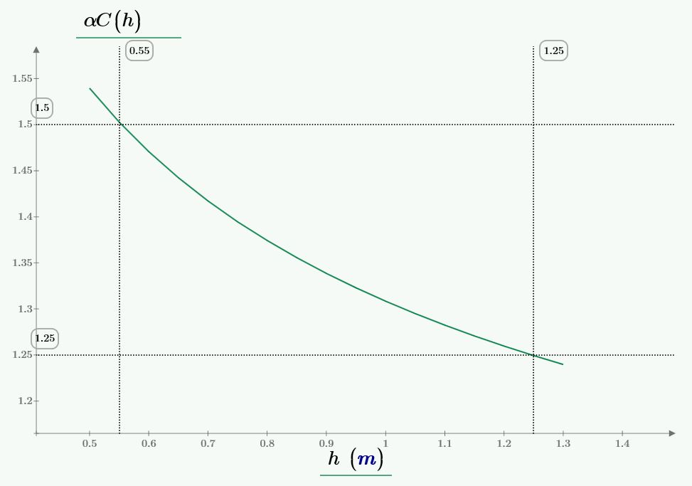
Concrete load factor \(\alpha C\) as a function of the concrete depth \(h\) measured in meters
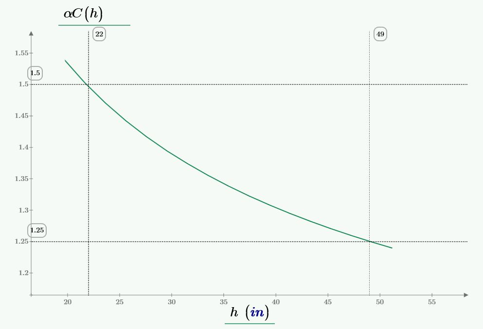
Concrete load factor \(\alpha C\) as a function of the concrete depth \(h\) measured in inches